Quick summary: In this guide, we looked at different types of building construction drawings that are important for any architectural project. From site plans to structural drawings, each serves a primary role in the successful realization of the building. Such knowledge of this types allows architects and engineers to convey their imaginations efficiently and to ensure correctness of construction. Keep reading to learn about the implication of these types of drawings for the building process.
Creating a building is like conducting an orchestra. All the elements have to be intricately designed and meticulously coordinated to ensure that the end product is nicely standing and ready to make a long-lasting impression.
The heart of this creative concert would definitely be the construction drawings and the blueprints for development. For this, this guide will not only tell you about the vivid world of the drawings of construction but will also make you aware of the different divisions of this music, enriching you with knowledge about the various practices and codes that shape the construction of tomorrow.
What is a Construction Drawing?
A construction drawing is both an illustration and a diagram, which depicts in detail the architectural and engineering plans for a building. It is visual design working as the plan for contractors and builders to help them put it practically in place as described in the designed plan.
Architects, structural engineers, and designers produce construction drawings to translate their ideas and instructions to builders in the process of construction. This set is a crucial component of construction because a design serves as a guide for all participants in the process of building.
A Detailed Introduction to Construction Drawings
The building drawers come in before the first nail is nailed, and the opening of the outlook, the construction drawers let the builder’s vision unfold. Each mark on the graphic is essential and crucial in that it carries many dimensions that escape mere distances and numbers.
These architectural plans interpret an eloquently extravagant story of the building’s structural body, soulfully revealing it through mechanical minds, artistic touch, and financial fingerprints.
The Foundation of Design
Construction drawings are not some traditional forms of expression but are instead the architect’s communicative foundation. They not only share design concepts but also give precise construction, building systems, and appliance information. They also create a permanent record called As-Built, which describes the site conditions.
In each piece, every feature is surgically carved, time frames are determined, and plans are calibrated, which results in a visible memorial of creativity and engineering.
The Blueprint’s Evolution
3D building design has changed a lot in recent years after the process of generating them. From the inception of hand- hand-draftsmanship to the uprising of computer-aided design (CAD) to Building Information Modeling (BIM), the purpose has always been to accurately prove designers’ vision in a language that builders can understand.
Beyond adaptability and accuracy, this warp speed takes us to the next level. In this place, design and build worlds exist but not separately; rather, they are an undivided entity that has no room for being out of context.
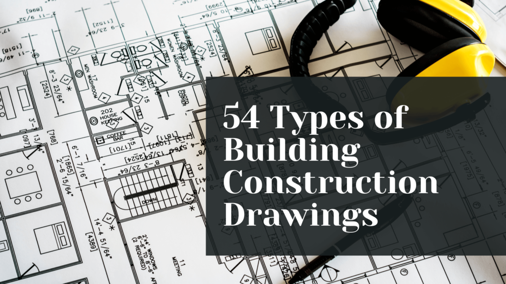
Top 54 Types of Construction Drawings
Understanding the various construction drawing types is crucial. In this guide, we cover and succinctly explain 54 essential construction drawing types for 2024, ensuring you’re well-informed on the topic.
1. Architectural Site Plan
An all-inclusive 2D drawing map depicting the site where the construction would happen should show landmarks like the location, old and surrounding buildings, and essential amenities.
2. Grading Plan Drawing
It is a task meant to represent the proposed building site after the existing lands are the building site. Considerations in this regard include the elevations of the sites, the drainages, and the natural features.
3. Landscaping and Hardscaping Plans Drawing
These sketches extract all sorts of beautiful and exquisite concepts. Through them, I learned a lot, from the selection of plants to the materials of pavements and even the overall concept of the space. The full-inclusive approach guarantees that every single piece finds a place and, thus, creates a good-looking and comfortable outdoor environment.
4. Floor Plans Drawing
The most widespread kind of architectural drawing is linear drawings that depict the cross sections of a structure taken through a particular level.
Critical to the process, these blueprints are intended to visualize the buildings in detail, including the walls, doors, windows, and other essential features like layout. Such maps perform an indispensable function as they allow architects, engineers, and builders to grasp the spatial organization and structural details of the building so the building design can be both practical and pleasing to the eye.
4. Reflected Ceiling Plans Drawing
These plans issue a view of every room, including sometimes, like when you take off the roof and see the whole thing from above. They prepare drawings that are as detailed as possible; they show electrical networks and light fixtures as well as lighting elements; that is, they provide a complete picture of an interior for better planning and execution.
5. Interior Design Plans Drawing
These pictures are drawn very carefully, showing in detail various floor plans and their arrangement, thinking both about the decor and the usage of the space.
They function as indispensable means for designing the proper arrangement of utensils, the balance of functionality and serenity of space, and all this with the aim of developing an environment that is at the same time beautiful but also comfortable.
6. Elevations Drawing
The renderings in this exhibit are two-dimensional replications of the building’s façade, imagining the structure’s visual nature from every angle.
These 3D views were developed to offer comprehensive viewing of the exterior design prior to actual building construction when people can see the design from different sides. Thus, they enable an in-depth examination and understanding of the architectural idea.
7. Sections Drawing
On the other hand, they highlight one structure at a time by very accurately and detailed sculpting from one level to another and, in return, the horizontal layout. This approach provides a more lucid explanation of single structural elements and simultaneously illustrates how they work together to form a harmonious and architectural design.
8. Wall Sections Drawing
Precise drawings of each wall in itself are a must for the ability to perceive what materials are to be used and for a deeper understanding of the internal systems, like electricity, water supply, and plumbing. These illustrations retain an essential role for constructors, being the basis for the building process and providing the specified precision and speed.
9. Details Drawings
This work is of utmost importance as it provides the precise specifications of all the architectural elements so that there is no confusion about whether the particular gates, doors, and windows should follow certain dimensions and be made of suitable material or not.
10. Stair and Railing Floridness
The given drawing represents an exceptional resource, as it entails wholesome details about the most sophisticated interior design element of a fixed structure.
11. Roof Plans Drawing
These drawings give a perspective of the roof from the top down in terms of roof structure, construction details, and roof elements, e.g., drainage and penetrations.
12. Foundation Plans Drawing
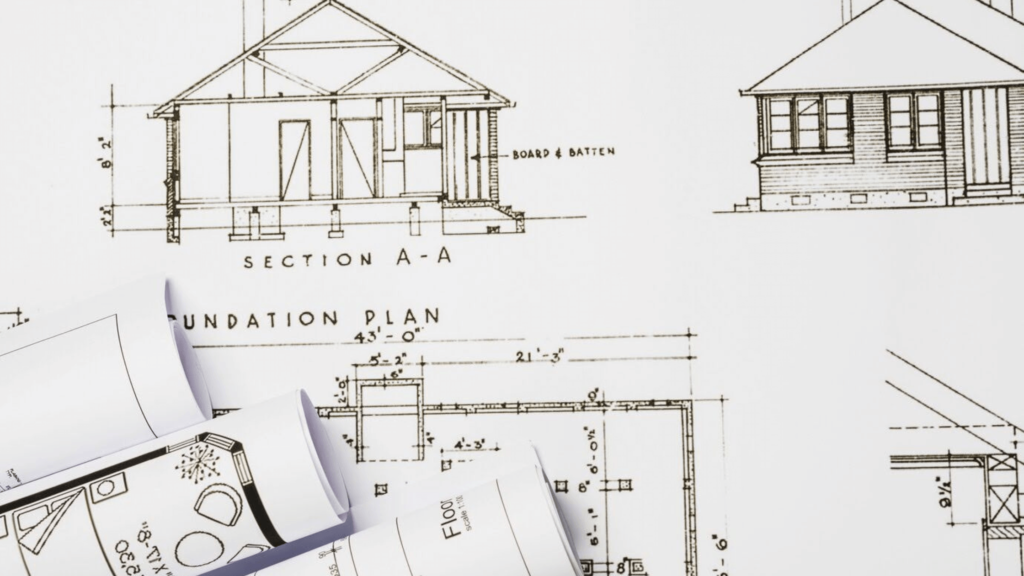
Some of the most important features in these drawings are the foundation and detailed ideation of the shape, size, and growth, as well as different design elements of the skeleton. They show in great detail how the ground pylon’s architecture is designed to interact with the ground and how this interaction guarantees the building’s integrity and longevity.
13. Framing Plans Drawing
As the document states, both ground and roof structures are delivered through the flooring and ceiling drawings, including the defined mounting of the rafters at their accurate spacings. It realizes which type of joints and sizes of beams, joists, and trusses should go where to have good stability and support.
14. Millwork Drawings
A millwork drawings service is a specialized service that provides detailed drawings for custom-made woodwork items. The service can be offered by architects, designers, or specialized drafting companies.
They are a set of pages where the shop will specify, describe, and display custom interior woodwork, including cabinetry and suspended mantels. They create specific lengths, widths, and materials that later would be needed for a carpenter or a millworker to fabricate the pieces.
15. Window and Door Programme Schedule-Sketches
A list containing all window and door dimensions, including types and material specifications for each project.
16. Room Finish Schedule Drawing
Inventory of finishes for each room, not forgetting paints and flooring materials, are also involved, along with treatment types.
17. Structural Drawings
This type of documentation will illustrate the composition of the structure in the form of load-bearing and non-load-bearing elements.
18. Foundation Structural Drawings
In-depth construction plans that are in line with the geotechnical engineering data, together with the materials and technical information, are a must.
19. Detail Drawings for Special Conditions
Any out-of-normal state and the exceptional structure details to be built generally need separate drawings in order to be installed correctly.
20. Mechanical Drawings
They demonstrate the organization of mechanical systems, which include HVAC (heating, ventilation, and air conditioning), sanitary, and fire protection.
21. HVAC Drawings
One of the indispensable aspects of climate control was shown in these drawings, which indicated the location and details of heating, ventilation, and air-conditioning devices.
22. Plumbing Plans Drawing
The layout for the pipes, fittings, appurtenance, and on-site management to convey water or excrete drainage into or within the property.
23. Fire Protection and Safety Plans Drawing
Some plans include mapping the escape routes, the position of the firefighting equipment, and the design of the sprinkler system.
24. Electrical Drawing
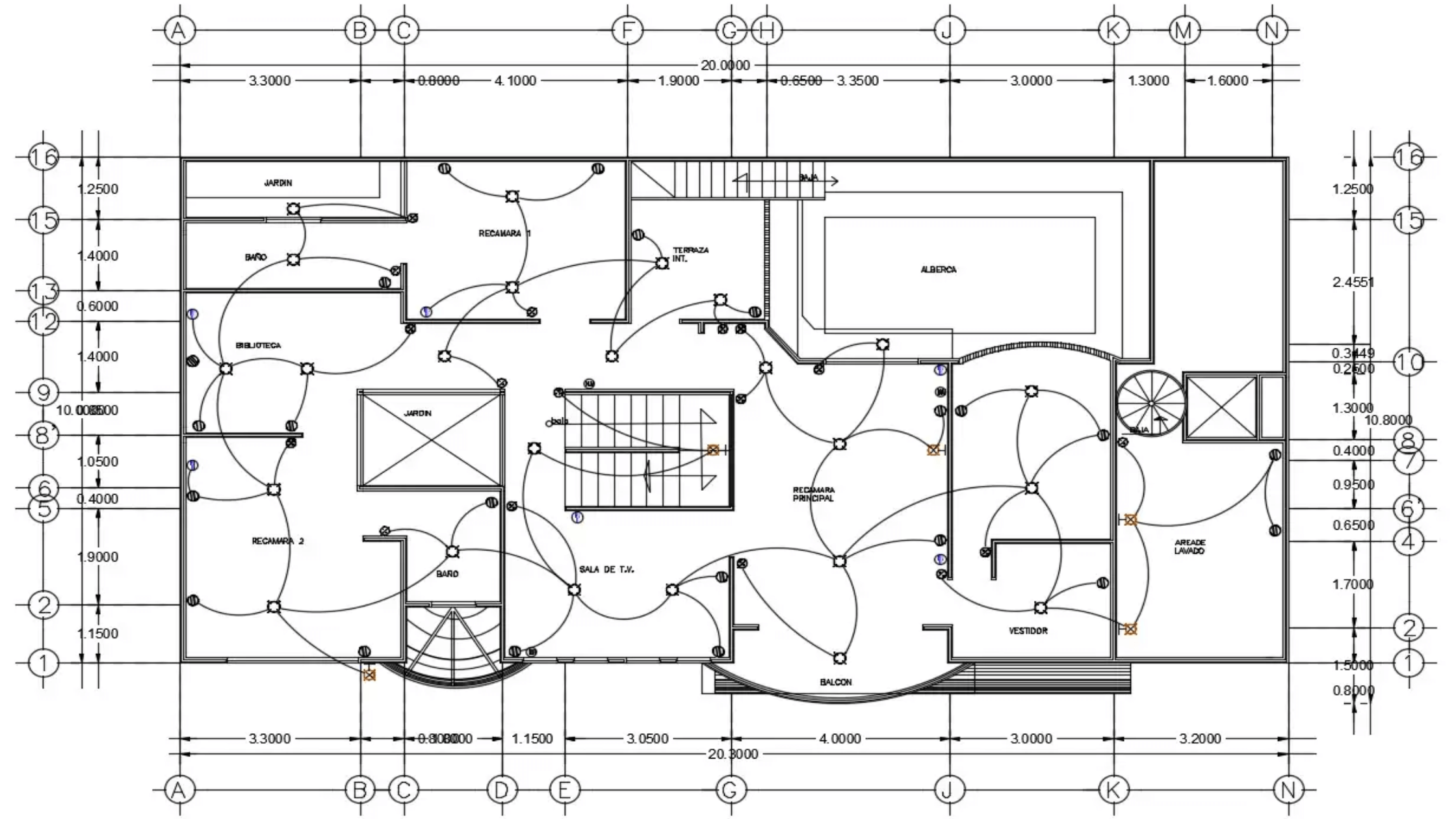
Electrical drawings are essential for planning and installing electrical systems within a building, including the layout of lighting fixtures, switches, outlets, and the routing of electrical wiring. These detailed schematics ensure that the electrical infrastructure is safely and efficiently integrated into the overall design and complies with all relevant codes and standards.
25. Power and Lighting System Plans
There is an increased level of sophistication in showing the panels’ locations and their implementation regarding the electrical system operation, which involves efficiency and lighting.
26. System Plans Drawing
Illustrations of the scheme that low-voltage systems will have, such as that involving data and communication wiring, intercoms, and security.
27. Surveillance Layouts Drawing
Plans for the security state usually establish cameras, sensors, and control stations, which require extensive integration of technology.
28. Communications Systems Drawings
They will be responsible for system designs that ensure simple integration of critical railway communication systems into building layout.
29. Energy Systems Drawing
These representations of eco life have renewable energy production systems like wind turbines or solar panels captured to showcase how these systems can be integrated.
30. Audio/Video Systems Diagrams
In this modern era of entertainment, embedding the multimedia device in the construction is crucial, as detailed drawings demonstrate.
31. Lighting Control Diagrams
Lighting systems that cover both aesthetics and function must have their design and control developed for these reasons.
32. Mechanical and Electrical Schedules Drawing
Those charts will be represented by list tables that will reflect the exact timings, costs, and required materials for the installation of MEP systems. Such activities result in the balancing act for tracking progress and allotting the allocated amount.
33. Landscape Plans Drawing
Integrated designs of outdoor areas combine hardscaping components such as walkways and patios with varieties of greens in the planting.
34. Swimming Pool Design Drawing
Engineering such that the technical drawings and specifications must be met in order to execute a successful project.
The drawing of a project involving the construction of a pool or water feature will state the size, shape, and kinds of materials that will be used in its construction.
35. Irrigation Plans Drawing
Overall, the drawings for a landscaping project have to show the layout of watering systems and the health of plants. Therefore, these drawings are provided for irrigation systems as well as the whole landscape design.
36. Parking Layouts Drawing
Such plans indicate the area of each parking lot, access roads, lanes, and gates for vehicle access to a portion of the property or a building. It is different from all the other strategic ways of transport logistics because it includes considering traffic flow, accessibility, and zoning regulations.
37. Signage Plans Drawing
The designs of the signboards and ads that will be put up at the building, either on or around the building, ensure that everything is well placed and proper specifications are followed.
38. Material Schedule Drawings
Among our goals is to compile lists of materials with quantities and location details to facilitate work and easy management.
39. Finish Schedule Drawings
Plans like these should outline the date for the installation of furnishing fixtures and other equipment (FF&E).
40. Energy Compliance Drawings
They help buildings obtain all the necessary local and national permits for the energy code requirements. Nowadays, this task is becoming increasingly relevant.
41. Accessibility Compliance Drawings
By presenting a point where inclusiveness is focus, these sketches figure out how to fulfill all accessibility standards.
42. Land Use Approval Drawings
Drawings of the required scale that are likely to supplied to local zoning and planning authorities in order to get permits and approvals, including variances and site regulations subsequently.
43. SWPPP Drawings (Stormwater Pollution Prevention Plans)
Drawings depicting water and waste management measures aimed at reducing stormwater runoff and its contamination hazards should considered for environmentally friendly design.
44. Phase Drawings
For large-scale projects with sequential stages, these drawings will frozen and will keep the conditions and instructions of each stage.
45. Sustainable/LEED Compliance Drawings
Implementing sustainable design facets makes these schematics mandatory should the project aim for LEED certification or otherwise apply green building principles.
46. Elevation Drawings for Interfaces with Exterior Structures
An interior and an exterior element of a building usually intersect, and these drawings guarantee a proper fit and an appropriate sealing against the elements on the contacting surfaces.
47. Demolition Plans Drawing
Pictures that very accurately and explicitly explain the essential steps and the order of procedures necessary for eliminating the existing buildings or including the final touches to the construction site.
These illustrations clearly guide the construction team on which steps need to consider for site preparation and clearance practices in order to achieve maximum efficiency and promote safety from their procedures.
48. Traffic Control Plans
These are obligatory permits for urban projects and necessarily indicate the looming road closures and detour management plans.
49. Earthquake Security Drawings
Drawings showing how structural members resist strong earthquake forces allow earthquake zones to be more controlled, which helps to resist disasters.
50. Building Envelope Details
The underlying mood and the image of the proper and ideal thermal performance of the house’s envelope are all depicted in these drawings, along with the details of the sealant and insulation.
51. Energy Modeling Diagrams
The schemes shall base on scheduled energy use and savings, which are map in these charts for compliance and accurate predictions.
52. Acoustic Construction Drawings
Moreover, specific plans for spaces that need particular acoustics are shown, which indicate construction and materials that resonate with the sound performance criteria.
53. Verification and Testing Drawings
Flatwork drawings are require from a documentation and control standpoint to ensure that verification and quality control test methods comply with technical specifications.
54. As-Built Drawings
These are the ultimate records of the project and document the building as it was actually construct, including any changes or deviations from the original plans.
By being cognizant of these various drawing types, professionals can better communicate the complexities associated with building construction, archive, and broadcast a project’s structural and design integrity.
Why opt for Chudasama Outsourcing Services for your construction drawing projects?
Choosing Chudasama Outsourcing Services for your construction drawing projects would bring several benefits, most importantly in CAD drawing services. Our team of highly experienced professionals employ our advanced CAD systems to facilitate the delivery of highly accurate and well-detailed drawings guaranteeing the success of your projects.
We feel very confident to complete the project on time without compromising on the quality to ensure that we are an excellent companion for both small and big-sized projects.
Furthermore, our pricing strategy is affordable to provide you with best value thus allowing you to channel the available budget in your projects. By devoting our time and resources to ensuring the maximum level of client satisfaction and through the tailoring of our services to meet each individual’s needs we are able to successfully deliver CAD drawings to our clients.
Conclusion
The future of construction drawings is bright and looks more interactive, accurate, and time efficient because of the development of new technologies.
Integrating these advancements will result in a much smoother drafting process and hence allow firms to not only compete but excel in the developing expectations of the market. For the best projects to complete, they should well thought-out and beautiful.
Chudasama Outsourcing, the complex nature of construction planning becomes precise and streamlined, turning visions into reality with expert knowledge and cutting-edge tools. We’re entering an era of living drawings and data-rich insights, marking a more intelligent, more connected, and more creative chapter in construction.